In the embedded system, the interface refers to the communication path or bus used to connect various integrated circuits with other peripheral devices. It is the connecting part and transfer station for information exchange between the microcontroller and the outside world.
Why do we need interfaces between the MCU and peripherals?
There are four major reasons listed as follows.
Introduction to Universal Interfaces
UART
Universal Asynchronous Receiver-Transmitter, commonly known as UART, is a full-duplex asynchronous transceiver, which is a part of computer hardware and transfers data between serial communication and parallel communication. As a chip converts parallel input into serial output, UART is usually integrated for connection with other communication interfaces.
A unique advantage of UART is that it can transfer data between devices using only two wires. In UART communication, two UART tranceivers directly communicate with each other. The UART transmitter converts the parallel data from the CPU into serial data and then transmit them to the receiving UART transceiver. The receiving UART transceiver hence converts the serial data back to parallel data for the receiving device. Data flow from TX pin of sending UART to RX pin of receiving UART is shown as in Figure 1:
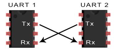
Figure 1. Diagram of UART Communication Connection
The UART communication protocol data frame is described as follows:

Figure 2. UART Data Frame
UART Communication Principle
Data transmission process: In an idle state, the circuit is at a high level. When receiving the data transmission command, pull down the level of the circuit for one data bit for time T, and then send the data from lower digits to higher digits. After the data transmission is completed, the parity bit and stop bit (stop bit is at a high level) are sent to wrap up the transmission of a data frame.
Data reception process: In an idle state, the circuit is at a high level. When an edge of voltage dropping is detected in the circuit, it suggests that data transmission has started. And the data is received from lower digits to higher digits according to the agreed baud rate. After that a parity bit is received and compared to see if the transmission is correct. If it is correct, the subsequent device is notified to prepare to receive the data or store it in the cache.
In embedded design, UART is used for communication between the MCU and auxiliary equipment, such as communication between car audio and external APs. Or the communication between the MCU and the PC including the monitoring debugger and other devices, such as EEPROM.
In BLE modules, UART transparent transmission has almost become a standard feature. The serial transparent transmission module is extremely convenient to use. Developers do not need to understand how the Bluetooth protocol stack is implemented. They can easily develop wireless products with the BLE Modules featuring UART transparent transmission.
Shenzhen RF-star Technology, as a wireless IoT module manufacturer, provides the UART serial BLE modules based on SoCs of TI CC2640 CC2642 CC264X, CC26X2, Silicon Labs EFR32BG22, Nordic nRF52832 nRF52810, and other domestic solutions. Supporting Bluetooth 4.2/5.0 in data transmission and reception, they are of industrial grade, compact in size, and boast of ultra-low power consumption. They facilitate users fast developing Bluetooth applications at extremely low cost.
SPI
SPI is the abbreviation of Serial Peripheral Interface. SPI interface is mainly used between EEPROM, FLASH, real-time clock, network controller, LCD display driver, AD converter, digital signal processor & decoder, and other devices.
高速全二重同期通信バスとして、SPI はチップに 4 つのピンしか必要としないため、IC のピンと PCB レイアウトのスペースも節約できます。
その 4 つの主要なピンは次のとおりです。
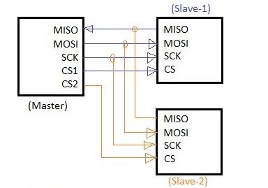
図 3. SPI マスター/スレーブ接続
1 つの SPI クロック サイクルで、データ送信は次の操作を実行します。
これはシフト レジスタによって実現されます。マスターとスレーブはそれぞれシフト レジスタを持ち、両方がリング状に接続されています。クロック パルスのペースで、データは最初に最高位の桁、最後に最低位の桁の順序でマスター レジスタとスレーブ レジスタから移動し、次にスレーブ レジスタとマスター レジスタに移動します。レジスター間での転出が完了すると、レジスター間でのコンテンツの交換が完了します。データ送信を図 4 に示します。
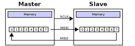
図 4. SPI データ送信
SPI 動作では、クロック極性 (CPOL) とクロック位相 (CPHA) の 2 つの最も重要な設定です。クロック極性はクロックがアイドル状態のときの電圧レベルを設定し、クロック位相はデータの読み取りとデータ送信のクロック エッジを設定します。
マスターとスレーブは同時にデータを送信し、両方とも同時にデータを受信します。したがって、それらの間の正しい通信を保証するには、SPI のクロック極性とクロック位相が同じである必要があります。
次の図は、4 つのモードでの通信プロセスを示しています。
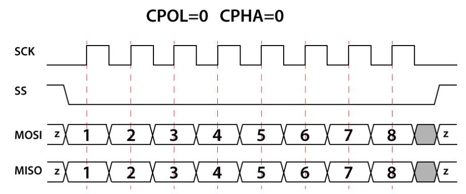
図 5. CPOL=0、CPHA=0
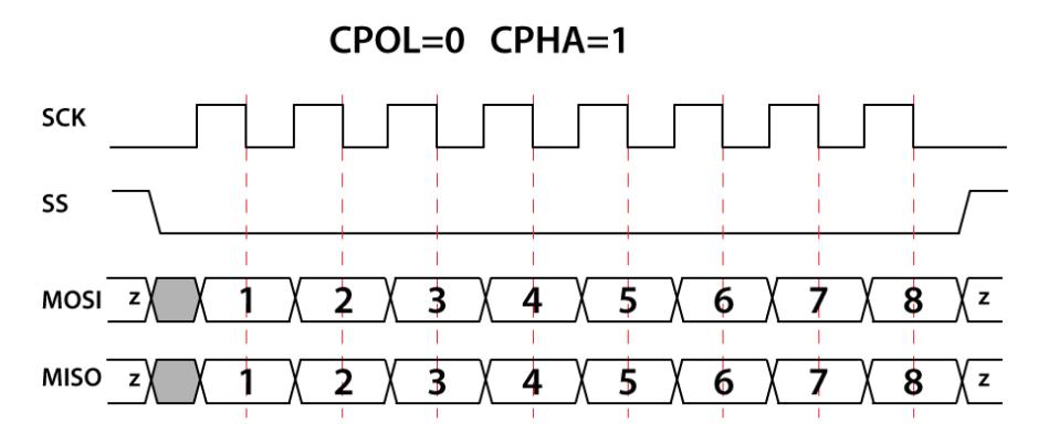
図 6. CPOL=0、CPHA=1
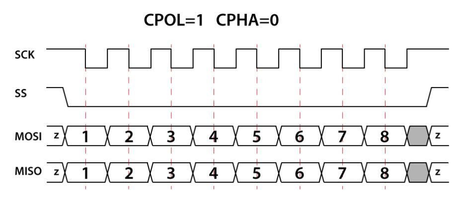
図 7. CPOL=1、CPHA=0
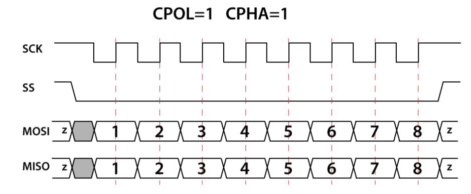
図 8. CPOL=1、CPHA=1
次の章では、I2C、USB、ADC、CAN などの他の周辺インターフェイスについて詳しく説明します。乞うご期待!
私たちに関しては
Shenzhen RF-star Technology Co., Ltd. (RF-star) は、無線周波数デバイスに重点を置いているハイテク企業で、10 年以上にわたって低電力 RF 製品のサードパーティ IDH として Texas Instruments によって認定されています。 。RF-starはIoTワイヤレスを提供しますess モジュールと、BLE、Wi-Fi、Matter、Wi-SUN、Sub-1G、ZigBee、Thread などを含む幅広いソリューションを提供します。詳細については、同社の Web サイト https://www.rfstariot.com をご覧ください。 /または info@szrfstar.com までご連絡ください。